

I have finally reached a nice milestone in my 1-wire sensor board development: a small (50 x 50 mm), battery powered wifi board is able to send measurement data to Amazon AWS IOT.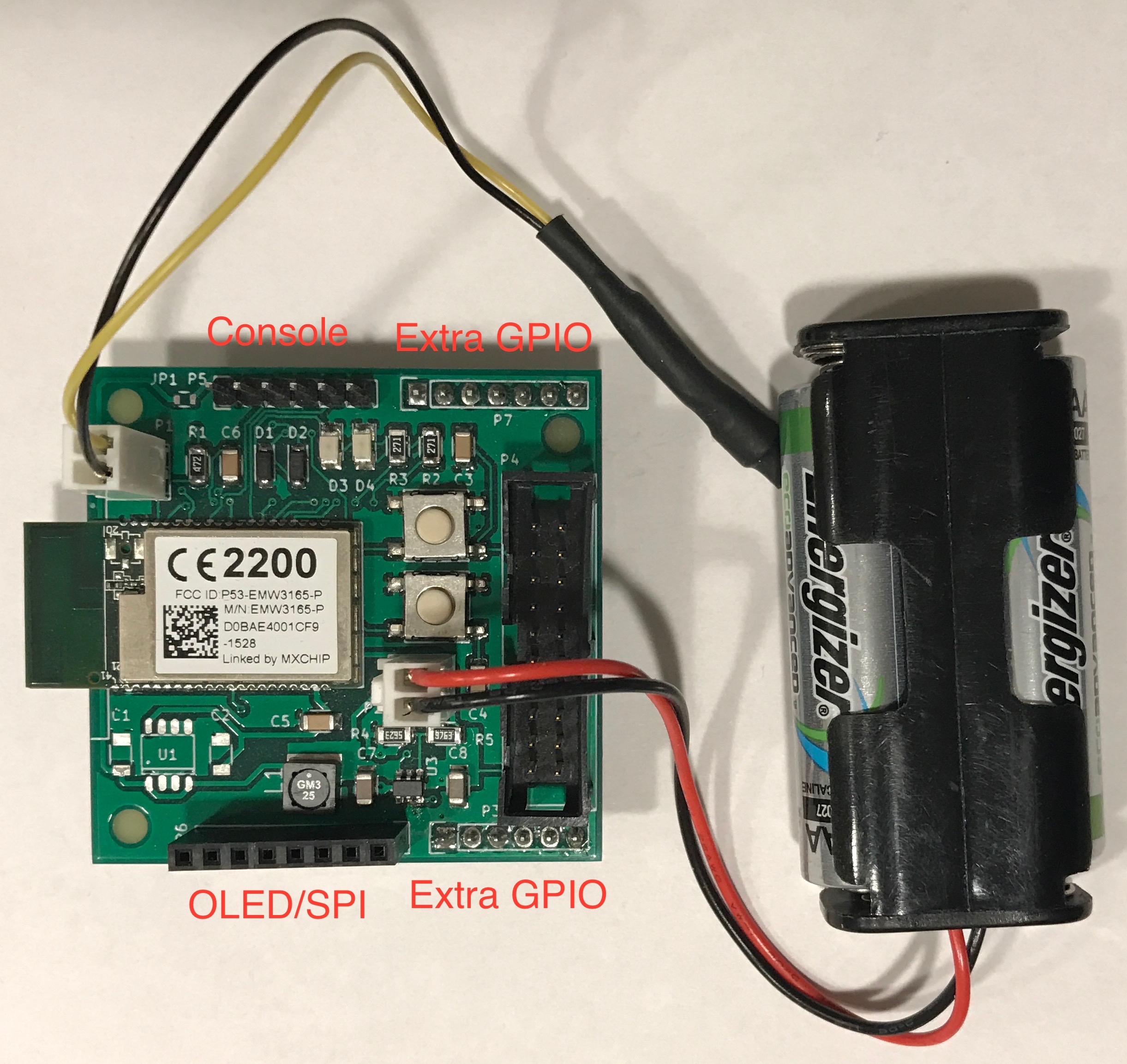
The board is designed with KiCad and manufactured by Seeedstudio. This is actually my first board using surface-mounted components and also my first board designed with KiCad. I was very surprised that the board actually worked (no smoke at all) after putting it together using a cheap reflow oven bought from ebay.
The board tries to be as simple as possible. In addition to EMW3165 module, there are just two buttons, two leds, 1-wire circuit and a power supply. Actually there are two power supplies: a boost converter using MCP1640 and LDO regulator using MAX604. The boost converter can power the board from two AA batteries, the LDO one needs at least three of them. The idea is that only one of the power supplies is soldered to the board (the board in the picture has boost converted soldered). The board has connectors for OLED display (SPI bus actually so it can be used to attach other things too) and console (pinout is compatible with FTDI usb-rs232 adapters). Leftover GPIO pins are wired to two connectors.
Well, how long is this thing going to run on batteries ? My current configuration measures temperature with DS1820 every ten minutes but instead of sending it immediately to a server the values are buffered and sent hourly. This allows the CPU to stay most of it’s time in stop mode. The STM32F411CE datasheet promises that max current in room temperature for stop mode is 14 to 38 μA. I did some measurements (with a cheap multimeter having μA range) and it looks that the best I was able to achieve is about 70 μA, which is a lot more than expected. However, datasheet for the wifi chip (CYW43362) reveals that it can suck 11 μA to 40 μA in sleep depending on VDDIO being present. On EMW3165 it apparently always is as there is no GPIO pin to control it. The external flash chip (MX25L1606E) is in deep power down mode during sleep so it consumes only about 2 μA. Sum all these up and we are at 56 – 80 μA.
But ~70 μA is not actually so bad. It takes about 5 seconds to send the data each hour. If the boost regulator runs approximately at 90% efficiency this gives more than year of battery life from 2 AA cells (about 2500 mAh per cell).
Firmware
I started developing board firmware with Broadcom Wiced SDK 3.5.2 and lwIP git master version but ended up with Cypress Wiced 4.10 and lwIP 2.0.1. I’m using only WWD driver layer from Wiced. Otherwise this is pretty common IOT device design – measure something, build JSON messages from that and deliver it to consumers with MQTT protocol. To be able to sync multiple sensor board measurements with each other, the module initializes real time clock with SNTP after it has succesfully joined wifi network.
Firmware has two different ways of doing the initial configuration: serial console or telnet session over wifi. To use wifi for initial configuration the module can be put into access point mode by keeping user button pressed for one second during startup. After that, an access point with name beginning with “EMW” should be visible. When connecting to it with PC it is possble to create telnet connection to 192.168.0.1.
Following commands can be used to configure access point and mqtt server which receives data from module:
esh> sta myap myappass
esh> mqtt --server=mqtt://mqtt.example.com
esh> mqtt --topic=sensordata
esh> mqtt --location=kitchen
esh> wr
esh> exit
After next reset the board will start sending values to given MQTT server once per hour.
So far this is just fine if using my own MQTT server in local network. But if data is to be sent to a cloud service like Amazon IOT, SSL/TLS support is required. My MQTT library (the ‘potato-bus’) has previously supported only unencrypted communications, but it was surprisingly easy to add SSL support with mbedTLS library. Only real problem was providing necessary entropy needed by cryptography functions as the STM32F411CE MCU does not have a random number generator. Luckily, mbedTLS supports use of nonvolatile seed, which is simply a file containing good quality random bytes from external source (like /dev/random). This file is generated during firmware build and included into firmware. Seed should be unique on each device so it is not a good idea to flash the same binary into multiple boards.
There are also some extra configuration steps for Amazon IOT services:
- Certificates (cert.der, privkey.der, rootCA.der) from Amazon must be placed into cert/ subdirectory before building firmware. Certificates must be in DER format (openssl can be used to convert if necessary).
- Mqtt URL (the –server option in mqtt command) should use mqtts:// to enable SSL/TLS.
SSL/TLS meas a little more processing during sending which results in somewhat decreased battery life.
Next steps
There is still room for improvement. In firmware, there is some code that is very similar to my other Wiced -projects. That would need to go into a library. For the circuit board, there are multiple small issues: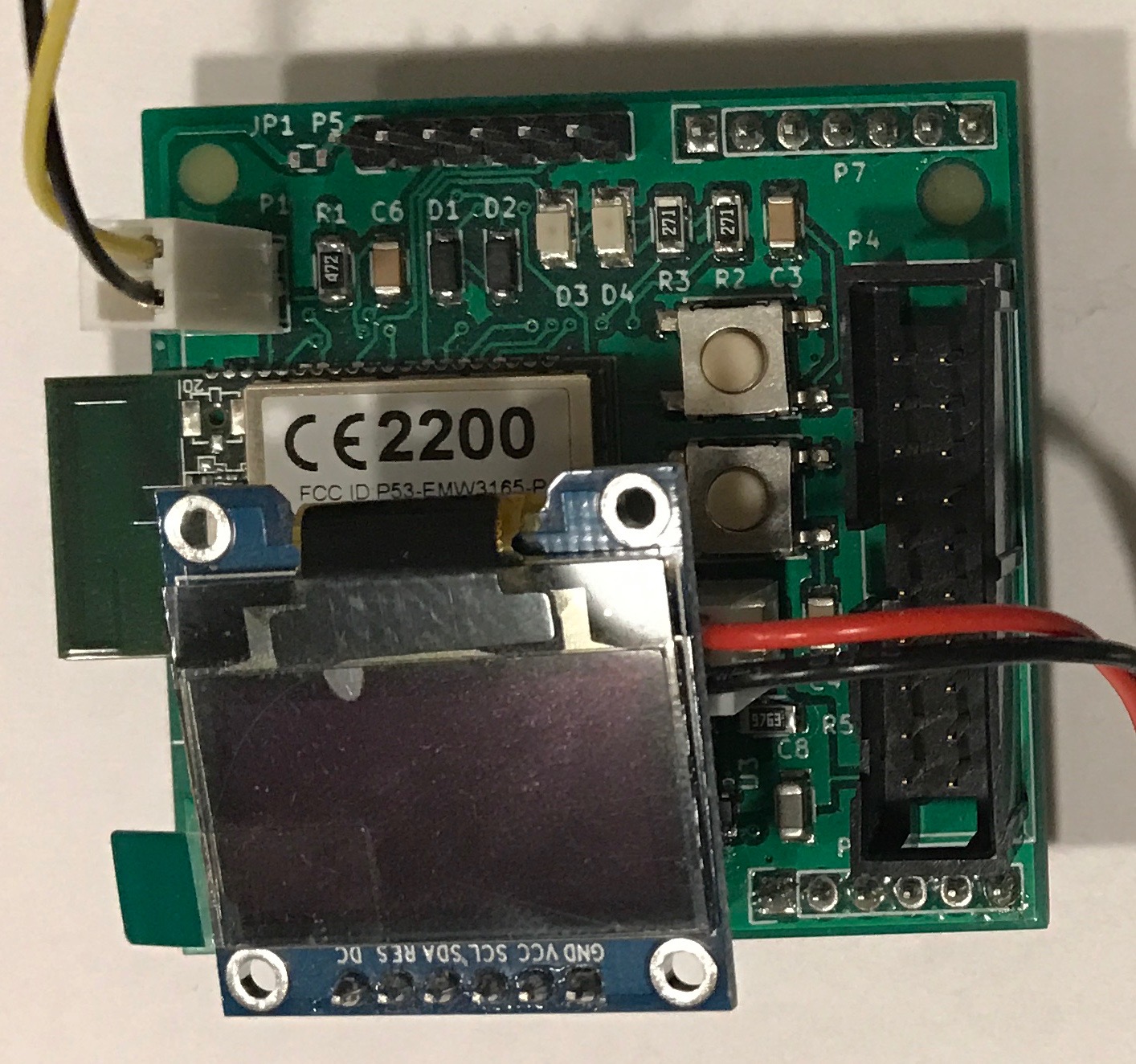
- JTAG/SWD connector takes a lot of room, I’ll have to replace this by smaller modern SWD connector.
- OLED Display connector (the black one at bottom in the picture) is OK, but the power connector is badly placed, making insertion of display module impossible without putting extra legs to it (see the picture).
- Buttons are difficult to press. Mainly because of the JTAG connector but if display is mounted it goes over the buttons.
- I forgot to connect Vbat+ to ADC input for battery level measurement.
- Angled connectors for battery & 1-wire would save space by making board taller.
Father of three 🙂
{ Electronics | Music | Computer | Motorbike } hobbyist.
Factory IT professional.
FreeBSD since day one.


