

Some months ago I built a simple wireless device to monitor temperature inside our household composting unit. Although the device worked initially well, I noticed two problems as time passed. First, the battery life wasn’t what I supposed it should be based on device data sheet and my measurements. Second, somehow moisture got into device no matter how well I tried to seal it with silicone. Continue reading “Compost Monitoring V2”
LPCXpresso IDE & Pico]OS
LPCXpresso is a low-cost development platform for NXP’s Arm-based microcontrollers. In addition to hardware boards it includes a quite nice eclipse-based IDE, which seems to use gcc as compiler. I really haven’t bothered very much about it myself until another hobbyist asked me about tips for running Pico]OS -based applications in that environment for his LPC1769 board.
I myself have been using Eclipse CDT (3.8 currently) and Yagarto (arm gcc toolchain for windows environment). I don’t have a LPC1769 board myself, but instead I have an Olimex LPC-1343 board I have used to test cortex-m port of Pico]OS. Both are cortex-m3 boards so they should be suitable for testing basic architecture functionality. Continue reading “LPCXpresso IDE & Pico]OS”
Rev2496 reverb repair
One day my old trusty Behringer REV2496 reverb processor refused to start up any more. It just sat there all possible leds lit doing nothing. Being unhappy about this I left it there and started thinking about some new device to replace it. The poor device must have seen me browsing thomann’s effect processor catalogue as it decided to start eventually after warming up.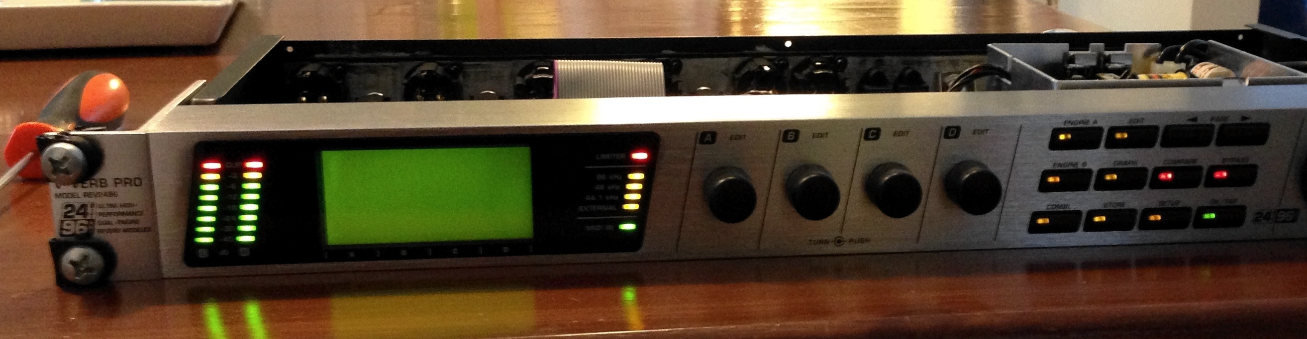
Ok, this is not an expensive, high quality audio processor, but I must admit that I have grown to like it during the years I have had it. There are some nice reverbs on it and it has also very good connectivity (optical, analog, aes/ebu). Because of this I decided to attempt repairing it. Continue reading “Rev2496 reverb repair”
Wireless KWh meter
After creating wireless compost monitor I was wondering what else could be done with the same card. I then saw a commercial about a gadget which displays house electricity usage in real time. The idea of the device is to help saving of energy. The gadget had a small box that apparently monitors how frequently the led on KWH-meter blinks (on our meter, it blinks once per 1 Wh) and sends that information to indoor visual display unit, which converts it into kilowatts.
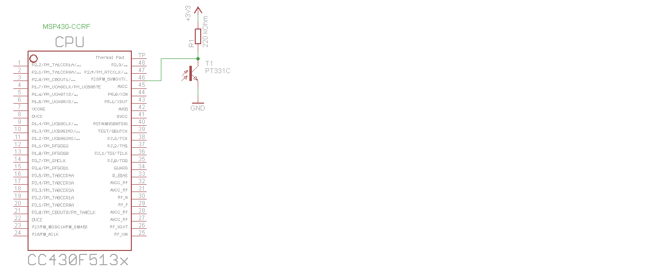
The commercial gadget looks really nice, but of course I had to make my own. The MOD-CCRF card is just perfect for system like this. I just added a phototransistor with pull-up resistor to keep on eye on the blinking led. After checking that my “eye” was really able to see the blinking led I added some code to existing wireless monitor application to calculate house electrical power from blink count. The monitor unit sends the data then to same wireless access point as the compost unit for saving results in database.
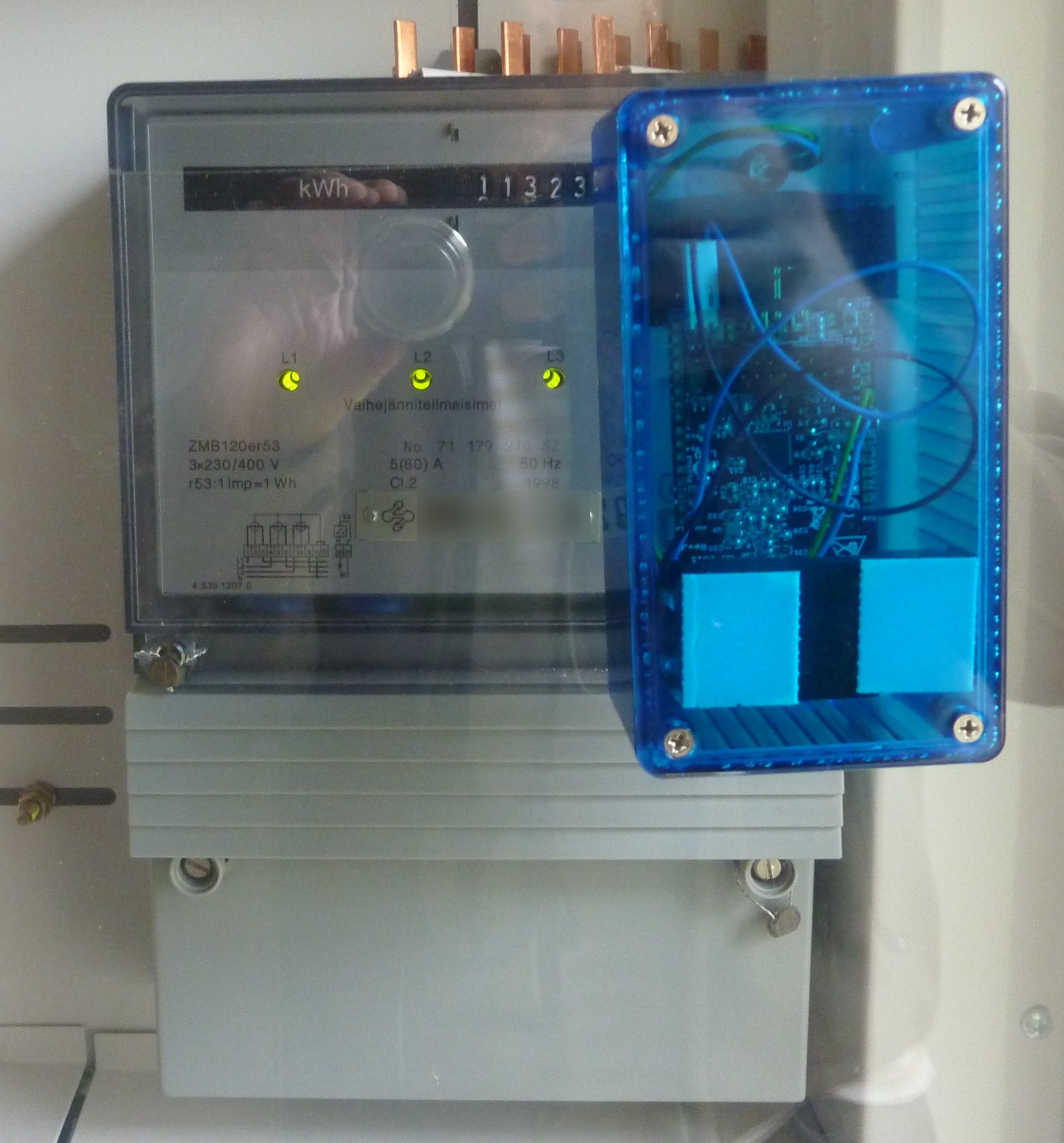
Our KWH meter is in a small ‘closet’ which has a transparent plastic door. By attaching velcro strips to the door and back of the monitor box I was able to position the unit exactly over the blinking led.
I also created a simple chart to monitor results (last trend at bottom of page).
Source code is available at Github in sensor-node project.
Heater circuit board
I decided to learn more about designing circuit boards with Eagle after reading an article about cheap chinese PCB manufacturer. Although there were some problems with their test boards the service is so cheap (about $1 for 5×5 cm board) that I wanted to try it.
For practice project I chose the pethouse heater described in previous blog. After spending some evenings with eagle I managed to produce required files to place an order at IteadStudio. The files were sent by e-mail and they confirmed that order was received. After that I didn’t got any messages from them, although I thought they were supposed to send some kind of shipping confirmation.
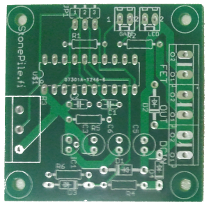 Anyway, after a few weeks I had a package at local post office. The board looks ok, but I noticed that I made some beginners mistakes (I should have read this before sending board to manufacturing) with my design when I started soldering parts to it. The bottom of board is filled with copper (a ground plane) but the isolation between solder pads is very small. As I forgot to specify it’s width the minimum from design rules was used (6 mils). Another mistake with ground plane was that I used thermals on high-current solder pads also. I had to remove solder mask around those pads and fill the gap with solder in order to be able to pass required current (about 6 A).
No other problems (none with manufacturing), so I replaced the prototype board on heater with this one and the system still works 🙂
The minimum order was 10 boards, costing a little more than $10 with shipping. Now I have extra 9 boards for future PWM controller projects!